Hydraulic power units (otherwise called hydraulic power packs) are independent frameworks that normally comprise of an engine, a liquid repository, and a siphon. Its responsibility is to apply the hydraulic tension needed to work engines, chambers, and other hydraulic framework parts.
What Is a Hydraulic Power Pack and How Does It Work?
A hydraulic framework utilizes encased liquid to communicate energy starting with one source then onto the next, coming about in rotational, direct, or power movement. The power unit/pack gives the essential power to this liquid transmission.
Hydraulic power units, in contrast to ordinary siphons, utilize multi-stage compression organizations to move liquid and every now and again incorporate temperature control frameworks. A hydraulic power unit’s mechanical properties and particulars decide the sorts of undertakings for which it very well might be utilized.
Pressure limitations, power limit, and supply volume are largely fundamental components that decide the working of a hydraulic power unit. Its actual characteristics, like size, power supply, and siphoning strength, are additionally significant elements to consider. Taking a gander at the primary parts of a regular model utilized in modern hydraulic frameworks will assist you with bettering handle the functioning standards and plan parts of a hydraulic power unit.
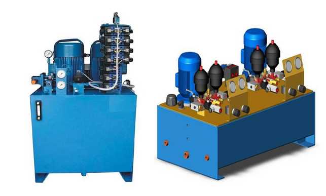
Parts of Hydraulic Power Pack/Unit Design
A major, hearty hydraulic power unit intended to work in an assortment of conditions will have specific plan includes that recognize it from an ordinary siphoning framework. Coming up next are a portion of the standard plan highlights:
Collectors: Accumulators are compartments that can be associated with hydraulic actuators. They accumulate water from the siphoning component and use it to supplement the engine siphoning framework by building and keeping up with liquid strain.
Engine Pumps: A hydraulic power unit may have a solitary engine siphon or many engine siphons, each with its own aggregator valve. Just one of the siphons in a numerous siphon framework is regularly turned on at a time.
Tanks: A tank is a capacity gadget with adequate volume to permit the liquid in the lines to deplete into it. Additionally, actuator liquid might should be depleted into the tank every so often.
Channels: Typically, a channel is fitted along the tank’s top. It’s an independent detour framework that has its own engine, siphon, and filtration framework. By actuating a multi-directional valve, it very well might be utilized to fill or exhaust the tank. Channels may regularly be supplanted while the power unit is running since they are independent.
Coolers and Heaters: To keep temperatures from expanding over functional standards, an air cooler can be situated close or behind the channel unit as a component of the temperature directing cycle. At the point when important, a warming framework, for example, an oil-based radiator, can be used to raise temperatures.
Hydraulic Controller Units: The hydraulic regulator unit is the administrator interface, which incorporates power switches, shows, and observing abilities. It is ordinarily seen as guided into the power unit and is needed for introducing and incorporating a power unit into a hydraulic framework.
What to Look for When Buying Hydraulic Power Motors
The engine is the power source, or central player, for most hydraulic power units, and it isn’t unexpected picked dependent on its speed, force level, and power limit. Over the long haul, an engine whose size and capacities supplement those of the hydraulic power unit can lessen squandered energy and increment cost-productivity.
The boundaries for choosing an engine change contingent upon the sort of power source utilized. For instance, an electric engine has an underlying force a lot more prominent than its working force, yet diesel and fuel powered engines have an all the more even force to-speed bend, conveying a moderately consistent measure of force at both high and low running velocities. Therefore, a gas powered motor might have the option to start a stacked siphon, yet not give sufficient power to carry it to working velocity in the event that it isn’t as expected coordinated with the hydraulic power unit.
As a guideline, the power rating for a diesel or gas engine utilized with a hydraulic power unit should be twofold that of an electric engine appropriate for a similar framework. Notwithstanding, the expense of the power devoured by an electric engine over its functional life expectancy generally overwhelms the expense of the actual engine, making it imperative to find a suitably measured unit that won’t squander energy utilization. On the off chance that the siphoning tension and fluid stream are set at a consistent rate, engine size can be estimated by the accompanying boundaries
At times, the hydraulic framework might require various degrees of tension at different phases of the siphoning system, implying that horsepower can be determined as the root mean square (rms) and a more modest engine might get the job done for the undertaking. Nonetheless, the engine should in any case have the option to meet the force necessity for the most noteworthy tension level in the cycle. Once the rms and the greatest force (counting introductory and functional levels) have been determined, they can be cross-referred to with an engine producer’s presentation outlines to decide if the engine is the vital size.
Working Process of Hydraulic Power Units
At the point when a hydraulic power unit starts working, the stuff siphon pulls hydraulic liquid out of the tank and moves it into a gatherer. This interaction proceeds until the strain inside the aggregator arrives at a foreordained level, so, all things considered a charging valve changes the siphoning activity to start circling liquid. This makes the siphon discharge liquid through a charging valve back into the tank at negligible strain. An uncommon single direction valve holds liquid back from streaming out of the collector, however assuming the strain drops by a critical sum, the charging valve reactivates and the aggregator is topped off with liquid. Farther down the line, a decreased strain valve controls the progression of oil moving to the actuators.
On the off chance that the collector is furnished with a quick stroking gadget, it tends to be associated with different gatherers to permit them to charge tension too. Regularly, a programmed indoor regulator or fan will be incorporated to assist with lightening rising temperatures. Assuming the liquid in the framework starts to overheat, a temperature switch can stop the engine siphon, which can likewise assist with topping off the tank in case its liquid level is excessively low. On the off chance that the hydraulic power unit has various engine siphons, a stream switch can have them substitute in the event of diminished liquid stockpile. Pressure switches can be utilized to control aggregator pressure and an observing framework can caution administrators when tension has dropped excessively low, raising the danger of power unit disappointment.
Conclusion: Manufacturing a hydraulic power pack is an intricate interaction. In this article we have attempted to separate it for you to comprehend the cycle and the intricacies engaged with the interaction. On the off chance that you are searching for a gas engine hydraulic power unit visit Rivelake for great item and dependability.


